Thursday, 12 May 2016

remote desktop to ubuntu

Step 1 – Install xRDP
Open Terminal (Crtl+Alt+T) and execute following commands :
sudo apt-get update
sudo apt-get install xrdp
Step 2 – Install XFCE4 (Unity doesnt seem to support xRDP in Ubuntu 14.04 although in Ubuntu 12.04 it was supported thats why we install XFCE4)
sudo apt-get install xfce4
Step 3 – Configure xRDP
In this step we modify 2 files to make sure xRDP uses xfce4. First we need to create or edit our .xsession file in our home directory. We can either use nano or simply redirect an echo statement (easier):
echo xfce4-session >~/.xsession
The second file we need to edit is the startup file for xRDP, so it will start xfce4.
sudo nano /etc/xrdp/startwm.sh
The content should look like this (pay attention to the last line and ignore . /etc/X11/Xsession):
#!/bin/sh

if [ -r /etc/default/locale ]; then
  . /etc/default/locale
  export LANG LANGUAGE
fi

startxfce4
Step 4 – Restart xRDP
To make all these changes effective, restart xRDP as such:
sudo service xrdp restart
Testing your xRDP connection
On the computer that will remotely control your Ubuntu machine, start you RDP client. Windows comes standard with a Remote Desktop client (mstsc.exe – you can start it from a command prompt, or find the shortcut to Remote Desktop under Accessories). Or Search 'remote' in start (Windows 7) Or 'remote' in search box in Windows 8.
Remote Desktop Connection
Whichever client you use, most work with either the computer network name or IP address of your Ubuntu machine.
To find the IP address on your Ubuntu box, type:
hostname -I
(note: this is a capital “i”)
Enter IP address of your Ubuntu Machine. For Example
enter image description here
Depending on your RDP client capabilities and settings (for example: Microsoft RDP Client allows automatic login), you might or might not see the login screen. Here we enter our Ubuntu username and password and click “OK”
xRDP – Login screen
You are done,enjoy
RDP – Your Ubuntu xfce4 desktop

How to create vlan on Linux (with Cisco Catalyst Switch)

In this article I want to share to you on how to create and configure vlan on Linux through Cisco Catalyst Switch.
Requirements:
1. Linux installed on a PC with one or more NICs (Network Interface Card). I use Centos 5.4 using 2.6.18-164.11.1.el5PAE kernel. It should be applicable on other Linux distros such as Slackware, Ubuntu, Fedora, Debian, etc.
2. Cisco Catalyst Switch 2950
3. 2 PC/Laptop running Windows/Linux/BSD/MacOSX
4. 3 straight cables
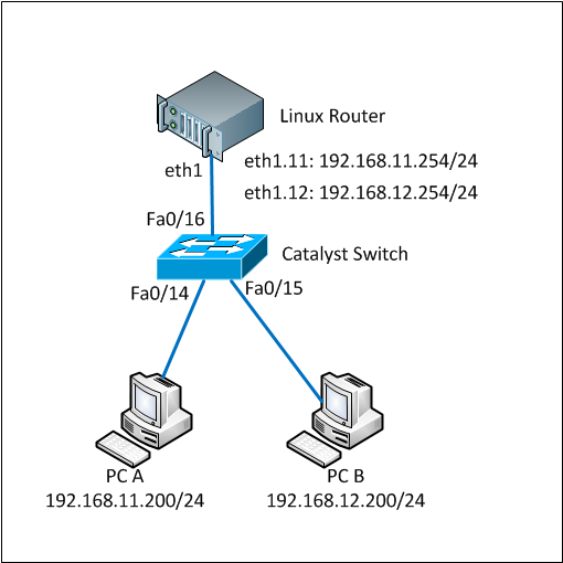
This tutorial is based-on network diagram below:
Linux VLAN Trunking Topology
Here are the full steps.
1. Load 802.1q module into the system
By default the 802.1q module is not loaded so we firstly have to load it. You can check whether it is already loaded or not by using ‘lsmod’ command.
lsmod |grep 802
If there is nothing shown by lsmod command, it means the module has not been loaded yet. Run ‘modprobe’ to load it.
modprobe 8021q
Make sure the module was successfully loaded by running the ‘lsmod’ again
lsmod |grep 802
8021q                  24649  0
If you see something similar like above, the 8021q has been successfully loaded.
2. Create vlan interface
We will use eth1 interface in the Linux box. We have to bring the interface up without IP address assigned to it before we can use it.
ifconfig eth1 0.0.0.0 up
We will create interface vlan 11 and vlan 12 on this eth1 interface. To create a vlan interface, use ‘vconfig add’ command as below:
vconfig add eth1 11
Added VLAN with VID == 11 to IF -:eth1:-

vconfig add eth1 12
Added VLAN with VID == 12 to IF -:eth1:-
These commands above will create devices eth1.11 and eth1.12 to your system. Linux will consider these as another network devices so you can configure and assign IP address like other.
You also see the vlan interfaces by typing ‘ifconfig -a’ command.
ifconfig -a

eth1.11   Link encap:Ethernet  HWaddr 00:30:48:BF:4E:BD
          BROADCAST MULTICAST  MTU:1500  Metric:1
          RX packets:0 errors:0 dropped:0 overruns:0 frame:0
          TX packets:0 errors:0 dropped:0 overruns:0 carrier:0
          collisions:0 txqueuelen:0
          RX bytes:0 (0.0 b)  TX bytes:0 (0.0 b)

eth1.12   Link encap:Ethernet  HWaddr 00:30:48:BF:4E:BD
          BROADCAST MULTICAST  MTU:1500  Metric:1
          RX packets:0 errors:0 dropped:0 overruns:0 frame:0
          TX packets:0 errors:0 dropped:0 overruns:0 carrier:0
          collisions:0 txqueuelen:0
          RX bytes:0 (0.0 b)  TX bytes:0 (0.0 b)
3. Assign IP address to the vlan interfaces
The vlan interfaces were successfully created on the previous step. Now we assign IP address on those interfaces using ifconfig command as below:
ifconfig eth1.11 192.168.11.254 netmask 255.255.255.0 up
ifconfig eth1.12 192.168.12.254 netmask 255.255.255.0 up
Make sure that the IP addresses were assigned successfully on the interfaces.
ifconfig eth1.11
eth1.11   Link encap:Ethernet  HWaddr 00:30:48:BF:4E:BD
          inet addr:192.168.11.254  Bcast:192.168.11.255  Mask:255.255.255.0
          UP BROADCAST MULTICAST  MTU:1500  Metric:1
          RX packets:0 errors:0 dropped:0 overruns:0 frame:0
          TX packets:0 errors:0 dropped:0 overruns:0 carrier:0
          collisions:0 txqueuelen:0
          RX bytes:0 (0.0 b)  TX bytes:0 (0.0 b)

ifconfig eth1.12
eth1.12   Link encap:Ethernet  HWaddr 00:30:48:BF:4E:BD
          inet addr:192.168.12.254  Bcast:192.168.12.255  Mask:255.255.255.0
          UP BROADCAST MULTICAST  MTU:1500  Metric:1
          RX packets:0 errors:0 dropped:0 overruns:0 frame:0
          TX packets:0 errors:0 dropped:0 overruns:0 carrier:0
          collisions:0 txqueuelen:0
          RX bytes:0 (0.0 b)  TX bytes:0 (0.0 b)
Until this step, creating and configuring vlans have been done on the Linux box. Now we are going to configure vlan and trunk on the Cisco Catalyst switch.
4. Configure cisco catalyst switch, add vlan database, configure interface access vlan and trunk
As said before, we use vlan 11 and vlan 12 on this tutorial. So those vlan must be added into the vlan database of the switch.
switch#conf terminal
Enter configuration commands, one per line.  End with CNTL/Z.
switch(config)#vlan 11
switch(config-vlan)#name test-vlan11
switch(config-vlan)#exit
switch(config)#vlan 12
switch(config-vlan)#name test-vlan12
switch(config-vlan)#exit
switch(config)#exit
switch#wr mem
Building configuration...
[OK]


switch#show vlan | include test-vlan
11   test-vlan11                      active
12   test-vlan12                      active
Vlan 11 and 12 have been successfully added to the database and active.
Now we have to configure 3 ports in the cisco catalyst switch. 1 port is for trunk between the switch and Linux box and 2 ports are for PC-A and PC-B.
We will use port Fa0/16 as trunk port and Fa0/14 and Fa0/15 as vlan access port connected to PC-A and PC-B respectively. Below are the commands:
switch#conf terminal
Enter configuration commands, one per line.  End with CNTL/Z.
switch(config)#int f0/14
switch(config-if)#description To_PC-A
switch(config-if)#swi acc vlan 11
switch(config-if)#no shutdown
switch(config-if)#exit
switch(config)#int f0/15
switch(config-if)#description To_PC-B
switch(config-if)#swi acc vlan 12
switch(config-if)#no shutdown
switch(config-if)#exit
switch(config)#int f0/16
switch(config-if)#description Trunk_To_Linux_Router
switch(config-if)#switchport trunk allowed vlan 11,12
switch(config-if)#switchport mode trunk
switch(config-if)#no shutdown
switch(config-if)#exit
switch(config)#exit
switch#wr mem
Building configuration...
[OK]
switch#


switch#show running-config interface f0/14
Building configuration...

Current configuration : 82 bytes
!
interface FastEthernet0/14
 description To_PC-A
 switchport access vlan 11
end

switch#show running-config interface f0/15
Building configuration...

Current configuration : 82 bytes
!
interface FastEthernet0/15
 description To_PC-B
 switchport access vlan 12
end

switch#show running-config interface f0/16
Building configuration...

Current configuration : 129 bytes
!
interface FastEthernet0/16
 description Trunk_To_Linux_Router
 switchport trunk allowed vlan 11,12
 switchport mode trunk
end

switch#
The configurations on both Linux box and Switch have completed.
Now it is the time to test whether PC-A and PC-B can ping to the same network on the Linux box. Make sure the cables are connected properly to each ports on the devices.
5. Test ping to Linux box using vlan ip address
Test from PC-A:
C:\Users\Fuad NAHDI>ping 192.168.11.254

Pinging 192.168.11.254 with 32 bytes of data:
Reply from 192.168.11.254: bytes=32 time=1ms TTL=64
Reply from 192.168.11.254: bytes=32 time
Test from PC-B:
C:\Users\Fuad NAHDI>ping 192.168.12.254

Pinging 192.168.12.254 with 32 bytes of data:
Reply from 192.168.12.254: bytes=32 time=2ms TTL=64
Reply from 192.168.12.254: bytes=32 time
6. Make everything active at boot
Everything we have done above is temporary configuration, meaning that it will be cleared from configuration when we reboot or shutdown the linux box.
To make it permanent or active at boot, simply add the following lines into the rc.local file (e.g Centos: /etc/rc.local ; Slackware: /etc/rc.d/rc.local):
modprobe 8021q
ifconfig eth1 0.0.0.0 up
vconfig add eth1 11
vconfig add eth1 12
ifconfig eth1.11 192.168.11.254 netmask 255.255.255.0 up
ifconfig eth1.12 192.168.12.254 netmask 255.255.255.0 up
Everything has been done. Now you should understand on how to create and configure vlan on Linux and Cisco Catalyst switch.

How to configure SPAN and RSPAN in Cisco Catalyst switches

Switched Port Analyzer (SPAN) allows you to send a copy of traffic passing through ports to another port on the switch. SPAN is important to mirror received or transmitted (or both) traffic on one or more source ports to a destination port for analysis. While SPAN is mirroring ports in the same switch, RSPAN(Remote SPAN) is mirroring ports in one switch to a port in different switch.
This post describes how to configure SPAN and RSPAN on Cisco Catalyst switches. On this example I use Cisco 2970.
1. SPAN
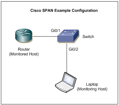
See the figure below, you would like to monitor the incoming traffic on port Gi0/1 using Wireshark connected to port Gi0/2.
 
Cisco SPAN Sample Topology
Here is the config you should have in the Switch
Switch#conf t
Enter configuration commands, one per line.  End with CNTL/Z.
Switch(config)#monitor session 1 source interface Gi0/1 rx
Switch(config)#monitor session 1 destination interface Gi0/2
Switch(config)#end
Incoming traffic passing through port Gi0/1 will be mirrored to port Gi0/2 and captured by Wireshark on Laptop connectedd to port Gi0/2.
2. RSPAN (Remote SPAN)
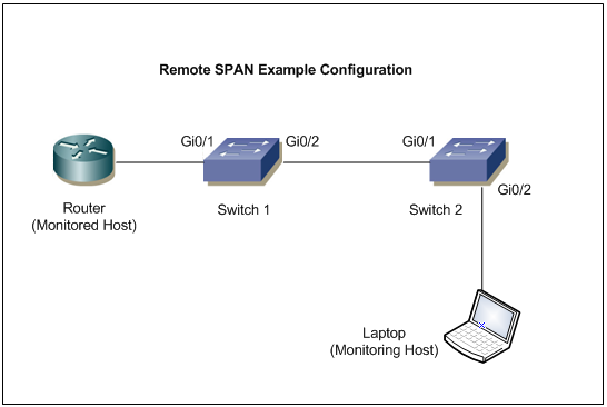
See the image below for sample topology. You would like to monitor traffic on port Gi0/1 in Switch1 using a Laptop connected to port Gi0/2 in Switch2. Both switches must be able to run RSPAN to work properly.
Create a VLAN that will be used as an RSPAN-VLAN on both switches. On this example we use vlan id 30 as the RSPAN-VLAN. Then allow the RSPAN-VLAN on the trunk port between Switch1 and Switch2.
 
Cisco RSPAN Sample Topology
Here is the config you should have:
Switch1 (Source switch)
Switch1#conf t
Enter configuration commands, one per line.  End with CNTL/Z.
Switch1(config)#vlan 30
Switch1(config-vlan)#name RSPAN-Vlan
Switch1(config-vlan)#remote-span
Switch1(config-vlan)#exit
Switch1(config)#monitor session 1 source interface Gi0/1 rx
Switch1(config)#monitor session 1 destination remote vlan 30 
Switch1(config)#end
Allow vlan id 30 on the trunk port Gi0/2
Switch1#sh run int g0/2
Building configuration...

Current configuration : 175 bytes
!
interface GigabitEthernet0/2
 description To-Switch2-port-Gi0/1
 switchport trunk encapsulation dot1q
 switchport trunk allowed vlan 10,20,30
 switchport mode trunk
end
Switch2 (destination switch)
Switch2#conf t
Enter configuration commands, one per line.  End with CNTL/Z.
Switch2(config)#vlan 30
Switch2(config-vlan)#name RSPAN-Vlan
Switch2(config-vlan)#remote-span
Switch2(config-vlan)#exit
Switch2(config)#monitor session 1 destination interface Gi0/2
Switch2(config)#monitor session 1 source remote vlan 30 
Switch2(config)#end
Allow vlan id 30 on the trunk port Gi0/1
Switch2#sh run int g0/1
Building configuration...

Current configuration : 175 bytes
!
interface GigabitEthernet0/1
 description To-Switch1-port-Gi0/2
 switchport trunk encapsulation dot1q
 switchport trunk allowed vlan 10,20,30
 switchport mode trunk
end
With the config above, incoming traffic passing through port Gi0/1 on Switch1 will be mirrored to port Gi0/2 onSwitch2 and captured by a traffic analyzer on Laptop connected to port Gi0/2.

Tuesday, 29 March 2016

Creating the Share on Linux

To set up a shared folder on Linux for Windows to access, start with installing Samba.
sudo apt-get install samba
After Samba installs, configure a username and password that will be used to access the share.
smbpasswd -a geek
Note: In this example, we are using ‘geek’ since we already have a Linux user with that name – but you can choose any name you’d like.
Create the directory that you’d like to share out to your Windows computer.  We’re just going to put a folder on our Desktop.
mkdir ~/Desktop/Share
Now, use your favorite editor to configure the smb.conf file.
sudo vi /etc/samba/smb.conf
Scroll down to the end of the file and add these lines:
[<folder_name>]
path = /home/<user_name>/<folder_name>
available = yes
valid users = <user_name>
read only = no
browsable = yes
public = yes
writable = yes
Obviously, you’ll need to replace some of the values with your personal settings.  It should look something like this:
Save the file and close your editor.  Now, restart the SMB service for the changes to take effect.
sudo service smbd restart
Your shared folder should now be accessible from a Windows PC.

Accessing the Linux Share from Windows

Now, let’s add the Linux share to our Windows Desktop.  Right-click somewhere on your Desktop and go to New > Shortcut.
Type in the network location of the shared folder, with this syntax:
\\IP-ADDRESS\SHARE-NAME
If you need the IP of your Linux computer, just issue the following command:
ifconfig


Accessing the Windows Share from Linux

You should be able to mount the shared folder by using the GUI in Linux, but it’s also very easy to do with the command line, and it’s easier to show a terminal example because it will work across many different distributions.
You’ll need the cifs-utils package in order to mount SMB shares:
sudo apt-get install cifs-utils
After that, just make a directory and mount the share to it.  In this example, we will mount the folder to our Desktop for easy access.
mkdir ~/Desktop/Windows-Share
sudo mount.cifs //WindowsPC/Share /home/geek/Desktop/Windows-Share -o user=geek

In case you need help understanding the mount command, here’s a breakdown:
sudo mount.cifs – This is just the mount command, set to mount a CIFS (SMB) share.
WindowsPC – This is the name of the Windows computer.  Type “This PC” into the Start menu on Windows, right click it, and go to Properties to see your computer name.


How to Mount ISOs and Other Disc Images on 


Linux
Ubuntu’s Unity desktop and GNOME include an “Archive Mounter” application that can mount ISO files and similar image files graphically. To use it, right-click an .ISO file or another type of disc image, point to Open With, and select “Disk Image Mounter.”
You can later unmount the image by clicking the eject icon next to the mounted image in the sidebar.
You can also mount an .ISO file or another disc image with a Linux terminal command. This is particularly useful if you’re just using the command line, or if you’re using a Linux desktop that doesn’t provide a tool to make this easy. (Of course, graphical tools for mounting ISO files and similar images may be available in your Linux distribution’s software repositories.)
To mount an ISO or IMG file on Linux, first open a Terminal window from your Linux desktop’s applications menu. First, type the following command to create the /mnt/image folder. You can create practically any folder you like — you just have to create a directory where you’ll mount the image. The contents of the disc image will be accessible at this location later.
sudo mkdir /mnt/image
Next, mount the image with the following command. Replace “/home/NAME/Downloads/image.iso” with the path to the ISO, IMG, or other type of disc image you want to mount.
sudo mount -o loop /home/NAME/Downloads/image.iso /mnt/image
To unmount the disc image later, just use the umount command:
sudo umount /mnt/image


Thursday, 17 March 2016

WPA2 TKIP or AES encryption ?


WPA and WPA2 encryption standards can sometimes be confusing.

WPA uses TKIP encryptionWPA2 uses AES, but can also use TKIP for backward-compatability (so it would accept WPAconnections).

In essence:
WPA = WPA with TKIP = PSK
WPA2 = WPA with AES = PSK2

When you set your router to use WPA2, you usually have the option to use AES, or TKIP+AES. When your router is set to "WPA2with TKIP+AES" it means that network devices that can use WPA2 will connect with WPA2, and network devices that can only useWPA will connect with WPA. The passphrase for both WPA and WPA2 will be the same. This option allows users to easily transition from WPA to WPA2. To set your router to use only WPA2, choose WPA2 with AES (do not use TKIP).

This mixed WPA2 TKIP+AES mode is sometimes called PSK2-mixed mode.

Note that many 802.11n devices will slow down to 54Mbps if you use older encryptions, such as WEP and WPA/TKIP security to be compliant with the specs.

Friday, 4 September 2015

Differences between STP and RSTP


49 Votes

The following table outlines the main differences between Rapid STP (802.1w) and the legacy STP(802.1d):
STP (802.1d)
Rapid STP (802.1w)
In stable topology only the root sends BPDU and relayed by others.In stable topology all
bridges generate BPDU every Hello (2 sec) : used as“keepalives” mechanism.
Port states
DisabledBlockingListeningLearningForwardingDiscarding (replaces disabled, blocking and listening)
Learning
Forwarding
To avoid flapping, it takes 3 seconds for a port to migrate from one protocol to another (STP / RSTP) in a mixed segment.
Port roles
Root (Forwarding)
Designated
 (Forwarding)
Non-Designated 
(Blocking)
Root (Forwarding)
Designated
 (Forwarding)
Alternate
(Discarding)Backup (Discarding)
Additional configuration to make an end node port aport fast (in case a BPDU is received).– An edge port (end node port) is an integrated Link type which depends on the duplex : Point-to-point for full duplex & shared for half duplex).
Topology changes and convergence
Use timers for convergence (advertised by the root):
Hello
(2 sec)
Max Age
(20 sec = 10 missed hellos)
Forward delay timer (15 sec)
– Introduce proposal and agreement process for synchronization (< 1 sec).- Hello, Max Age and Forward delay timer used only for backward compatibility with standard STP
Only RSTP port receiving STP (802.1d) messages will behaves as standard STP.
Slow transition (50sec):
Blocking (20s) =>Listening (15s) =>Learning (15s) =>Forwarding
Faster transition on point-to-point and edge ports only:Less states – No learning state, doesn’t wait to be informed by others, instead, actively looks for possible failure by RLQ (Request Link Query) a feedback mechanism.
Use only 2 bits from the flag octet:Bit 7 : Topology Change Acknowledgment.Bit 0 : Topology ChangeUse other 6 bits of the flag octet (BPDU type 2/version 2):
Bit 1 : ProposalBit 2, 3 : Port roleBit 4 : LearningBit 5 : ForwardingBit 6 : AgreementBit 0, 7 : TCA & TCN for backward compatibility
The bridge that discover a change in the network inform the root, that in turns informs all others by sending BPDU with TCA bit set and instruct them to clear their DB entries after “short timer” (~Forward delay) expire.TC is flooded through the network, every bridge generate TC (Topology change) and inform its neighbors when it is aware of a topology change andimmediately delete old DB entries.
If a non-root bridge doesn’t receive Hello for 10*Hello (advertised from the root), start claiming the root role by generating its own Hello.Wait for 3*Hello on a root port (advertised from the root) before deciding to act.
Wait until TC reach the root + short timer (~Forward delay) expires, then flash all root DB entriesDelete immediately local DB except MAC of the port receiving the topology changes (proposal)

Saturday, 30 May 2015

Cryptography in CCNA

Definitions


Crypotography

Cryptography (or cryptology; from Greek kryptós, "hidden, secret"; and graphein, "writing", or -logia, "study") is the practice and study of techniques for secure communication in the presence of third parties.

Cryptography is heavily based on mathematical theory and computer science practice; cryptographic algorithms are designed around computational hardness assumptions, making such algorithms hard to break in practice by any adversary. It is theoretically possible to break such a system, but it is infeasible to do so by any known practical means.


Key in Cryptography

In cryptography, a key is a piece of information (a parameter) that determines the functional output of a cryptographic algorithm or cipher. Without a key, the algorithm would produce no useful result. In encryption, a key specifies the particular transformation of plaintext into ciphertext, or vice versa during decryption.

Key Exchange

Key exchange (also known as "key establishment") is any method in cryptography by which cryptographic keys are exchanged between users, allowing use of a cryptographic algorithm.

Symmetric-key cryptography

Symmetric-key cryptography refers to encryption methods in which both the sender and receiver share the same key  (or, less commonly, in which their keys are different, but related in an easily computable way).

Symmetric key ciphers are implemented as either block ciphers or stream ciphers. A block cipher enciphers input in blocks of plaintext as opposed to individual characters, the input form used by a stream cipher.

The Data Encryption Standard (DES), the Advanced Encryption Standard (AES) and tripleDES are block cipher designs.  RC4 is a widely used stream cipher

This type of encryption scheme is often called "shared secret" encryption, or "secret key" encryption.

symmkey1.png


Public-key(asymmetric-key) cryptography

In a groundbreaking 1976 paper, Whitfield Diffie and Martin Hellman proposed the notion of public-key (also, more generally, called asymmetric key) cryptography in which two different but mathematically related keys are used—a public key and a private key. A public key system is so constructed that calculation of one key (the 'private key') is computationally infeasible from the other (the 'public key'), even though they are necessarily related. Instead, both keys are generated secretly, as an interrelated pair.

In public-key cryptosystems, the public key may be freely distributed, while its paired private key must remain secret. In a public-key encryption system, the public key is used for encryption, while the private or secret key is used for decryption.

asymmetric_encryption_diagram.png
The Diffie–Hellman and RSA algorithms, in addition to being the first publicly known examples of high quality public-key algorithms, have been among the most widely used.

Cryptographic hash functions

Cryptographic hash functions take a message of any length as input, and output a short, fixed length hash which can be used in (for example) a digital signature. For good hash functions, an attacker cannot find two messages that produce the same hash. MD4, MD5, SHA-1 and SHA-2 are some examples of cryptographic hash functions.

Using the same hashing function and message should produce the same hash; modifying any portion of the data should produce an entirely different hash. A user should not be able to produce the original message from a given hash, but theyshould be able to tell if a given message produced a given hash.
Hashing-Image.jpg


Let us see where cyptography is used in ccna.

Enable secret command

Enable secrets are hashed using the MD5 algorithm.

To determine which scheme has been used to encrypt a specific password, check the digit preceding the encrypted string in the configuration file. If that digit is a 7, the password has been encrypted using the weak algorithm. If the digit is a 5, the password has been hashed using the stronger MD5 algorithm.
For example, in the configuration command:
enable secret 5 $1$iUjJ$cDZ03KKGh7mHfX2RSbDqP.
The enable secret has been hashed with MD5, whereas in the command:
username jdoe password 7 07362E590E1B1C041B1E124C0A2F2E206832752E1A01134D
The password has been encrypted using the weak reversible algorithm.

service password-encryption command

this global command encrypts all clear text passwords with weaker encryption. You will be able to see digit 7 before
the hashed password in running config.

SSH

SSH provides strong encryption, server authentication, and integrity protection.  It may also provide compression.

We use the command crypto key generate rsa for configuring a router or switch for ssh. 
RSA is asymmetric encryption.SSH 1.99 is not an actual version but a method to identify backward compatibility.
I used to wonder when I enable ssh v2 IOS used to reply ssh 1.99 is enabled.
SSH uses encryption in 3 or 4 areas
1. Data encryption for hiding data(symmetric encryption like DES, 3DES, AES)
2.Key exchange(asymmetric key exchange like DH, RSA)
3.Data intregrity(hashing like md5 or sha-1)
4. Authentication (optional; the encryption  RSA)
There are 4 alternative methods used in ssh for authentication and they are
1.password authentication
2.public-key based authentication(DSSor RSA)
3.keyboard interactive
4.GSSAPI authentication

How key exchange works in ssh?
Ssh server and client negotiates which symmetric algorithm to implement for their session. These algorithm requires a symmetric key that both server and client should have it. They should not communicate shared key(symmetric key) in plain text between them. For this purpose they use key exchange algorithm. SSH may use DH key exchange or RSA key exchange. RSA in low end computers and DH in high end computers because DH requires more CPU processing.
RSA Key Exchange:
Ssh server will create a pair of public key and private key. The private key will not be send to the client . the public key (P) will be send to the clinet. The client generates a string of random byte K, client upon receiving the public key it will encrypt the K with P(public key) producing H.then H is sent to the server.Server then decrypts the H with private key to obtain K. Both server and client do same math on K,P and other parameters to produce shared key that is going to be used for encrypting the data. One point to note that RSA private key is never received by client.
keylessssl.png
you may right click on the image and chose open in new tab to view the image in full screen.
What is server and client in ssh?
suppose you want to configure R2 from R1.you start a ssh session from R1 to R2. in this scenario, R2 is ssh server and R1 is ssh client. you are required to configure ssh in ssh server and not required to configure ssh in ssh client in cisco devices.(this paragraph is purely based on my understanding)
RSA algorithm can be used for authentication and key exchange in ssh. When we use the command crypto key generate rsa , which one they are referring to is not clear to me. My strong guess is that it mentions about RSA key exchange and not RSA public key authentication.
The main use of hash(md5 or sha-1) in SSH is for data integrity purposes and to verify the authenticity of communication. These are used to ensure that the received message text is intact and unmodified.
Little about hashing
Hashing is not used for encrypting the data for hiding the data in communication and then sent to client. if they do so client cannot decrypt the hashed value. Hashing is always one way. You can encrpyt with hashing but cannot decrypt. some people have the idea that hashing is not encryption but it is. Hashing is used for data integrity. In SSH, data is hashed and output of hash is then appended to data before sending to client/server. The Client/Server on receiving this packet does same hash algorithm on data and verifies that the hash output locally generated is same as hash output appended with data. if matching data is not modified and if not matching data is modified during communication.
CHAP
We have studied CHAP authentication in PPP. In chap, a one-way hash function (MD5) is implemented in its process.
The Challenge‐Handshake Authentication Protocol (CHAP) is used to periodically verify the identity of the peer using a 3‐way handshake. This is done upon initial link establishment, and MAY be repeated anytime after the link has been established.

  1. After      the Link Establishment phase is complete, the authenticator sends a      "challenge" message to the peer.

  1. The      peer responds with a value calculated using a "one‐way hash"      function.

  1. The      authenticator checks the response against its own calculation of the      expected hash value. If the values match, the authentication is      acknowledged; otherwise the connection SHOULD be terminated.

  1. At      random intervals, the authenticator sends a new challenge to the      peer, and repeats steps 1 to 3.

note: CHAP sends md5 hash value. The password is know to both peer before hand. Instead of sending password in clear text they sent  Md5 hash value and then compared(locally genereted hash value of password and received hash value are compared).

VPN
VPN is a tunnel through internet. It is used for wan purpose and also used for safe web browsing by hiding your ip address. VPN uses IPsec or SSL protocol which provides encryption.GRE tunnel is also a tunnel but it is not encrypted. To use GRE tunnel as VPN we have to use IPsec in gre tunnel which we will study in CCNP.
There are two types of VPN and they are
1.site to site VPN which are further classified as intranet VPN and extranet VPN.
2.Remote access VPN which are further classified as corporate VPN and personal VPN.
Personal VPNs provide safe web browsing, anonymous web browsing(hides Ip address), unblocks blocked websites.You can try hotspot shield, ultrasurf freeware personal vpn softwares for safe web browsing. It may encrypt only the traffic in web browsers(IE, google chrome). For encrypting torrent application, you may have to purchase shareware vpn softwares. These kind of software make a tunnel with our PC to their server and then browse internet and so it looks like we are browsing from their LAN. these softwares mostly helpful in middle east and china where many wesites are censored.
pic_1.jpg

IPsec in VPN
Ipsec uses cryptography in 4 areas.
1. data encryption- hiding data(symmetric encryption like AES, 3-DES)
2. Authentication- verifying identities
3.hashing-protection aganist changes(md5, sha1)
4.key exchange(DH)
Ipsec after encrypting the data it encapsulates the packet and then sent through the tunnel. When we use vpn software for hiding ip address, this encapsulation step is the one that actually hides your ip address.(this sentence is purely my own observation)
In ssh, we saw client and server. In ipsec, we have peers(no client and server).
There are three alternative method for authentication in Ipsec and they are
1.kerberos version 5 authentication
2. preshared key authentication
3. public key authentication
In preshared key authentication they use symmetric encryption and in public key authentication they use asymmetric encryption. Kerberos builds on symmetric encryption and optionally may use asymmetric encryption during certain phases of authentication.
In ipsec, key exchange is maintained by IKEv1 or IKEv2(within the framework of ISAKMP) which uses DH key exchange algorithm. DH is not used for data encryption.
How key exchange is done in Ipsec?
It is different from SSH(RSA key exchange). Both the peers create the DH key pair. Then both the peers transfer their public key. DH  creates shared key by doing DH math with Private key locally created and public key of other peer. Both peer will create this shared key and it will be same. Suppose R1 and R2 are two peers. R1 creates R1-private and R1-public and R2 creates R2-private and R2-public. R1-public is send to R2 and  R2-public is send to R1. DH in R1will do math with R1-private and R2-public to create an output K.same way, DH in R2 will do math with R2-private and R1-public to create an output K. This output K obtained by R1 and R2 will be same. This output K is the shared key(symmetric key).
300px-Public_key_shared_secret_svg.png
Like ssh, Ipsec uses symmetric encryption for data confidentality and then exchange the key. Authentication is different in ssh and ipsec. Both ssh and ipsec uses hash for data integrity verification.

SNMPv3

SNMPv3 uses cryptography in 3 areas.

1.data integrity(md5 or sha1)

2.authentication(md5 or sha1)

3.privacy(DES,3DES,AES)

In SNMP, level name noAuthnoPriv is used to denote that there is no encryption for authentication and privacy(data hiding by encryption). if the level name is AuthnoPriv, only authentication is encrypted and privacy is not encrypted.if the level name is AuthPriv then both authentication and privacy is encrypted(this paragraph is based on my own observation)

GLBP

GLBP can also be configured for encrpted authentication(md5 or sha1).


Symmetric encryption is mostly used for data confidentiality and asymmetric encryption mostly used for authentication and key exchange. Asymmetric encryption is slower than symmetric is the reason it is not preferred for bulk data encryption. If we go for data confidentiality it is also considered wise to go for authentication and key exchange. What i learned so far is that, symmetric encryption for data encryption, asymmetric encryption for authentication and key exchange, hashing for data integrity and authentication.
I know key exchange in ssh or ipsec is not ccna syllabus, i discusses it here for more clarity. i didnt discuss anything about authentication, it is a vast topic.whenever i wrote my own sentence which is not verified with standard document i have quoted it by saying it is my own observation.ssh and ipsec is also very vast topic to study.i worked so hard to make this document.
I really appreciate Whitfield Diffie and Martin Hellman who came up with asymmetric cryptography for the first time in 1976. modern encryption is simply a complex mathematic algorithm which require a computer to compute it